Bike-Computer
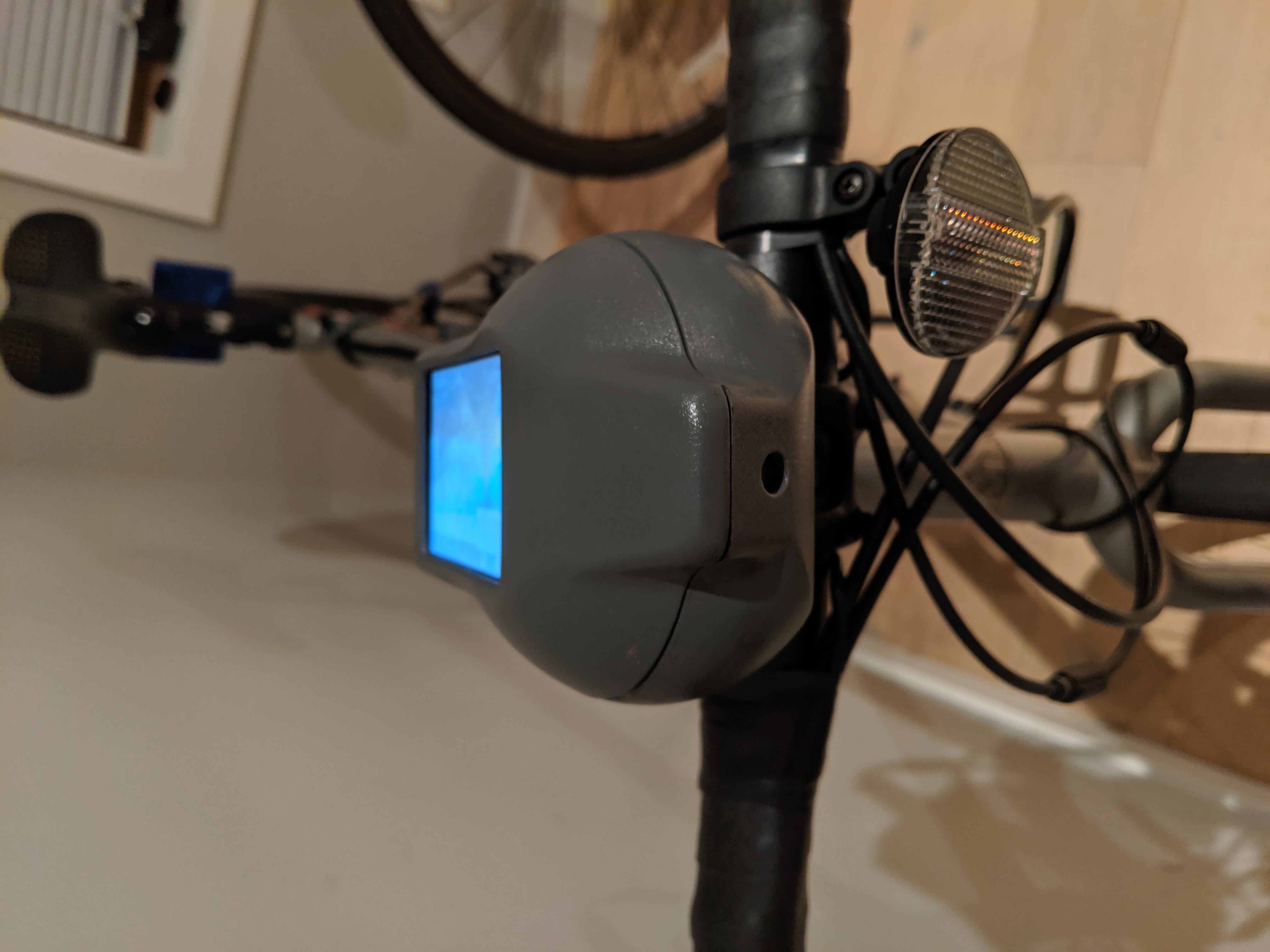
During the 2020 pandemic, I bought a bike. As I became a full fledged bike enthusiast, I started looking at all the add-ons I could fit up my ride with. It shocked me how expensive bike computers were, while being a fairly dumb piece of electronics. Since I had some extra Pi’s laying around, and wanting to dust off the 3D printer, I started designing up my own, with a couple extra features you won’t see off the shelf.
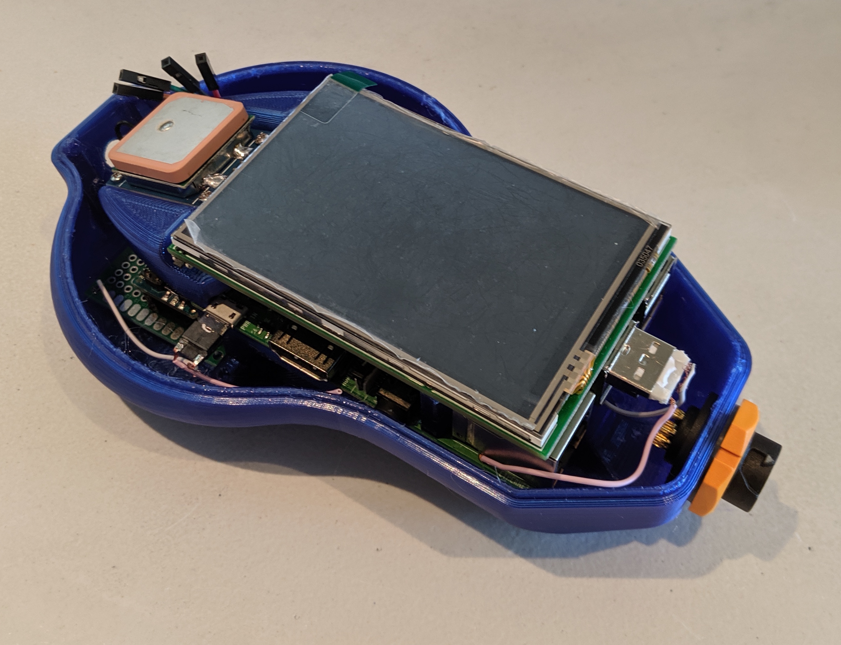
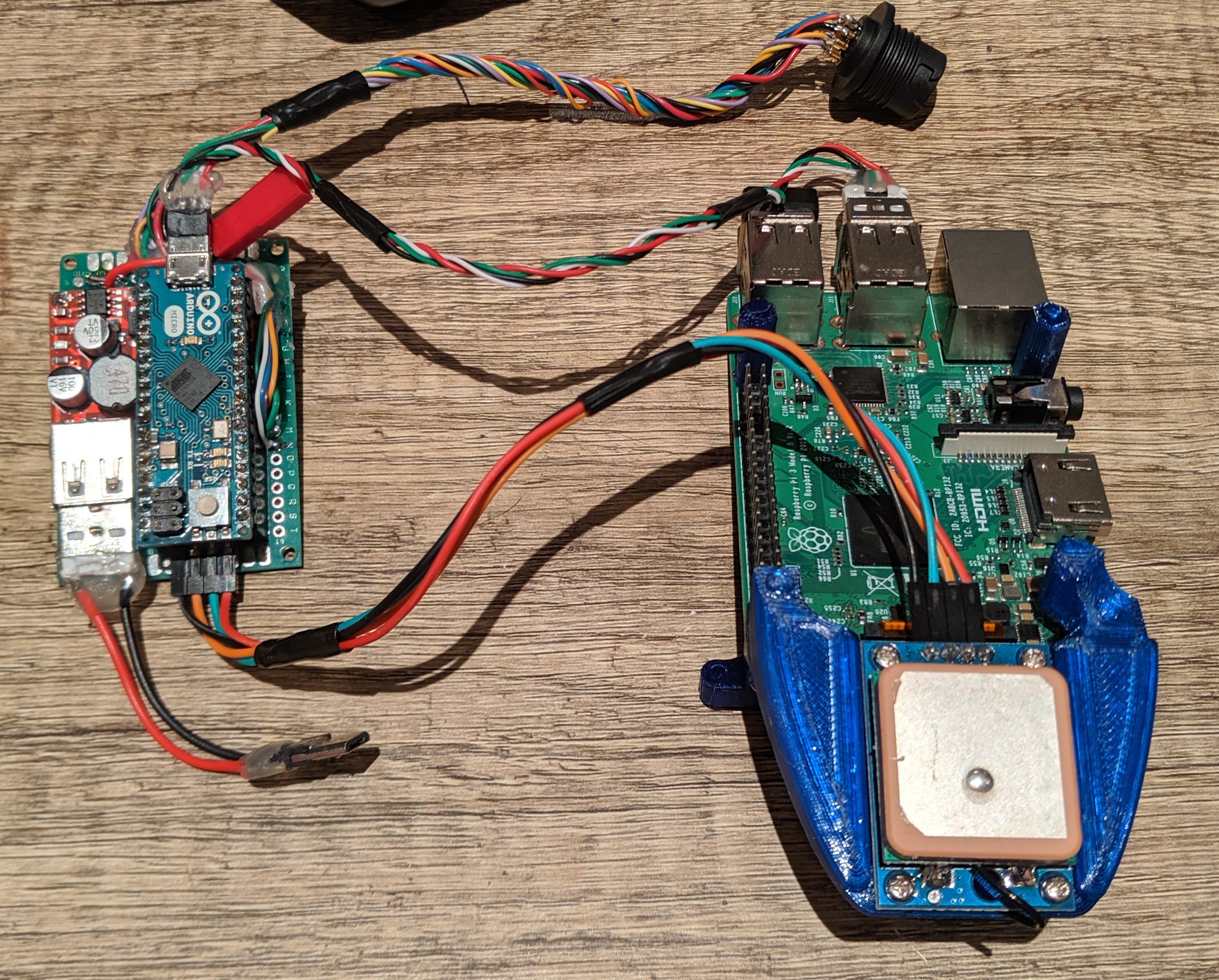
My system includes a Raspberry Pi, 3.5” touchscreen LCD display, a GPS module, integrated camera, an Arduino Mini, and a Li-ion battery with power regulator. There is a sealed 12 pin connector to relay signals to and from other features on the bike, including an IMU, rear blinker lights, and hall-effect sensors to measure speed and cadence. The total cost comes at around $130, which was totally worth the fun designing and building this.
Note, this build is still in progress, so you won’t see completed pictures just yet.
Mechanical Design
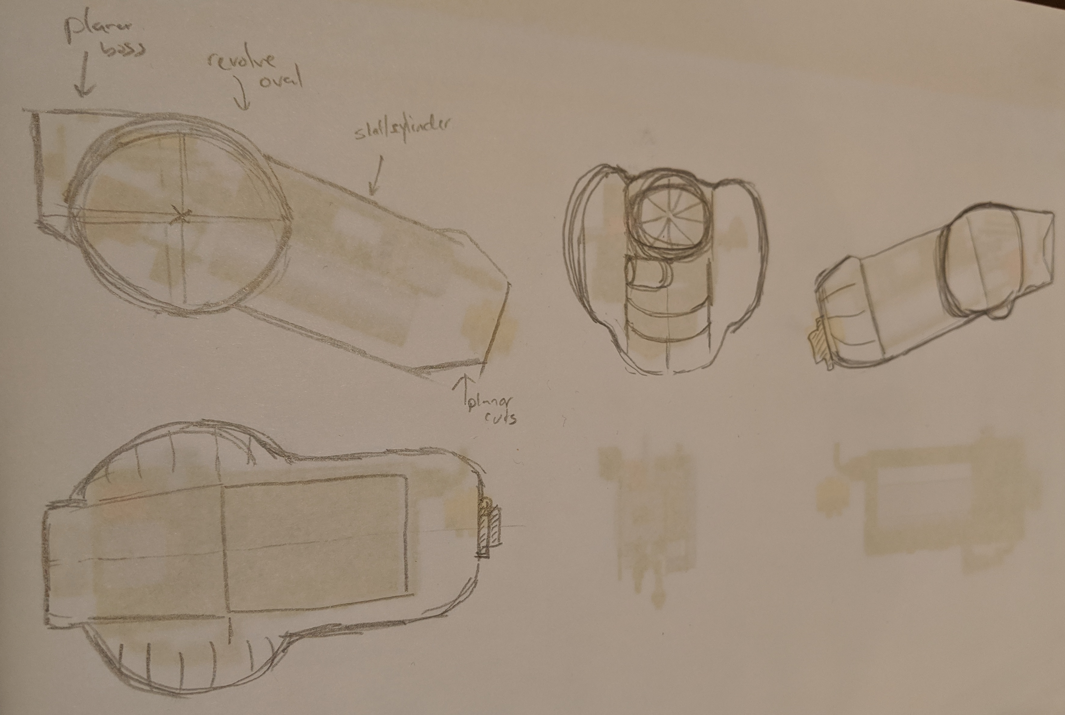
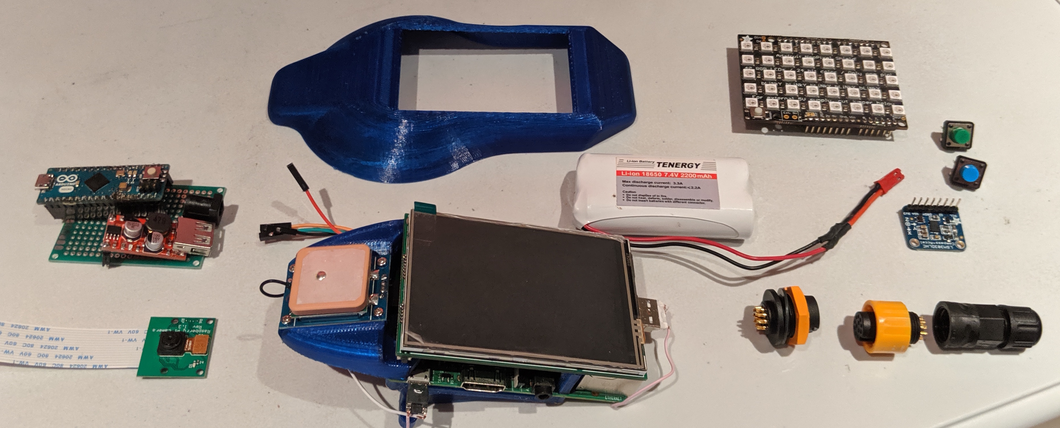
After defining the scope and features of the system, I shopped around for electronics parts that would be necessary to integrate. The first step was then to start laying all the components out in CAD, to see what would be a good packaging arrangement.
I wanted to keep the package thin and low to the bike handlebar, and opted to package some components on either side of the middle bar that I would be clamping the system to.
Once the sub components were roughly in position, I used a master modeling method within the assembly to create the structures necessary to mount and enclose them all. Happy with how it fit, I started my first print.
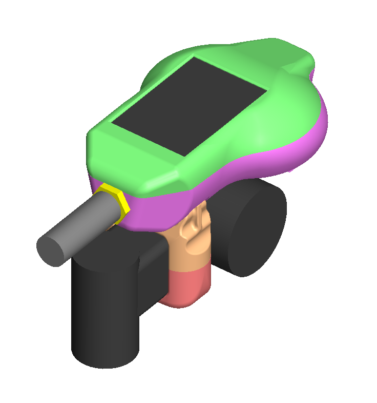
Engineering is an iterative process, and luckily the methods I was using to design and build are considered “rapid” prototyping. In this first build, I was immediately struck with how large the system looked on the bike, and potentially how much drag it would induce in my riding. I started immediately on a second packaging design after laying out this print.
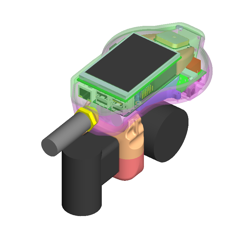
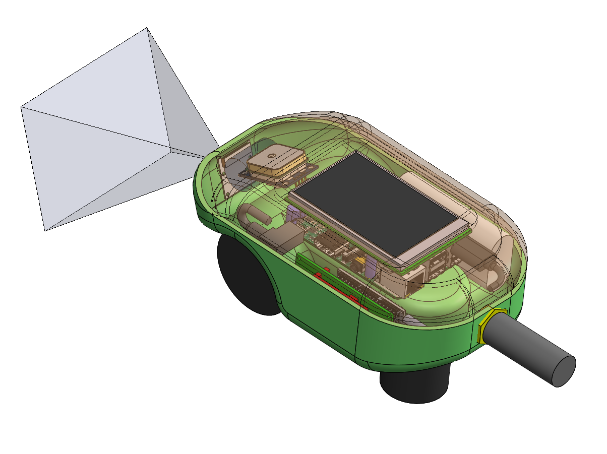
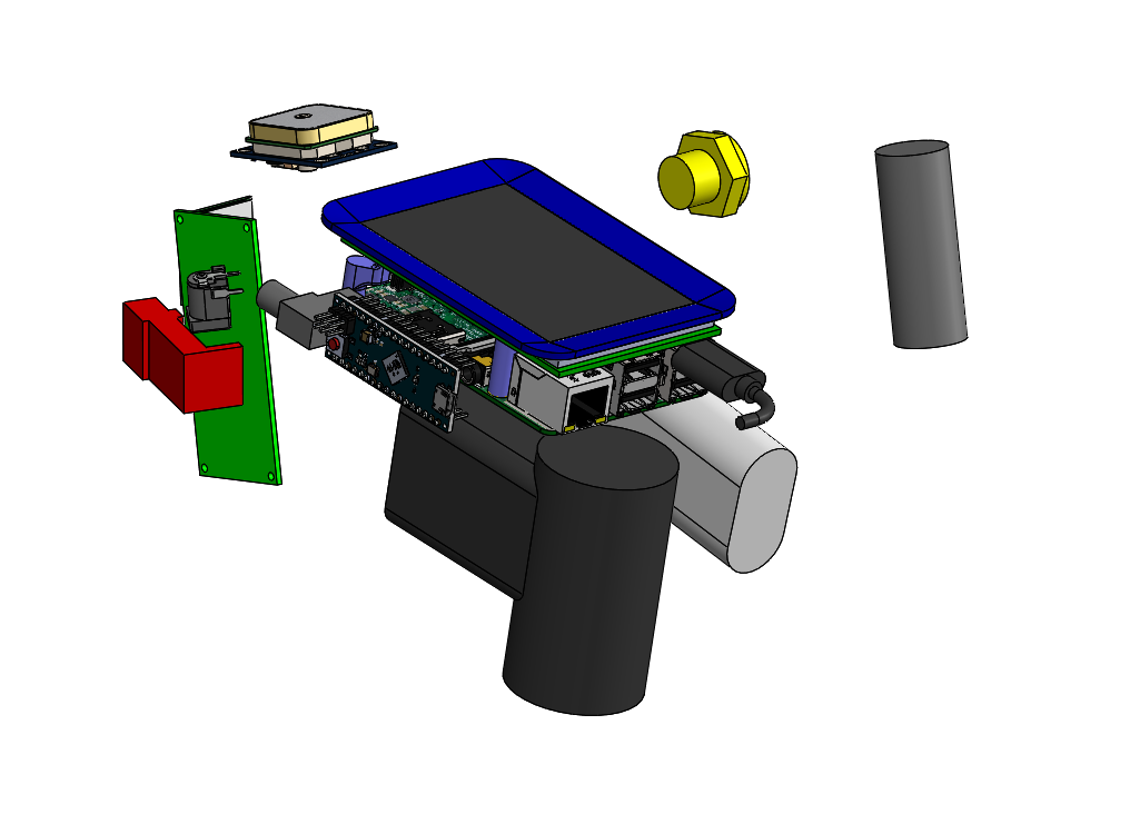
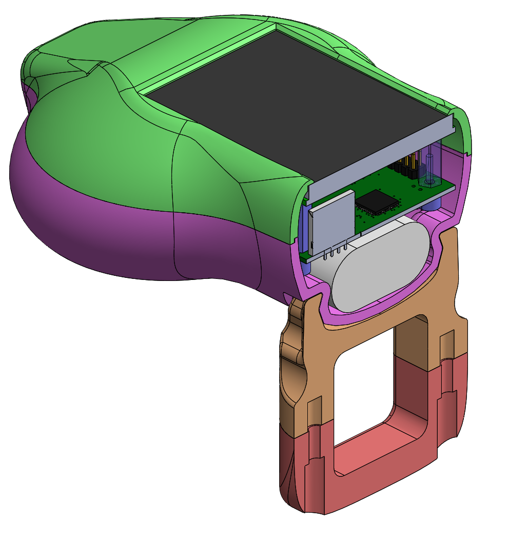
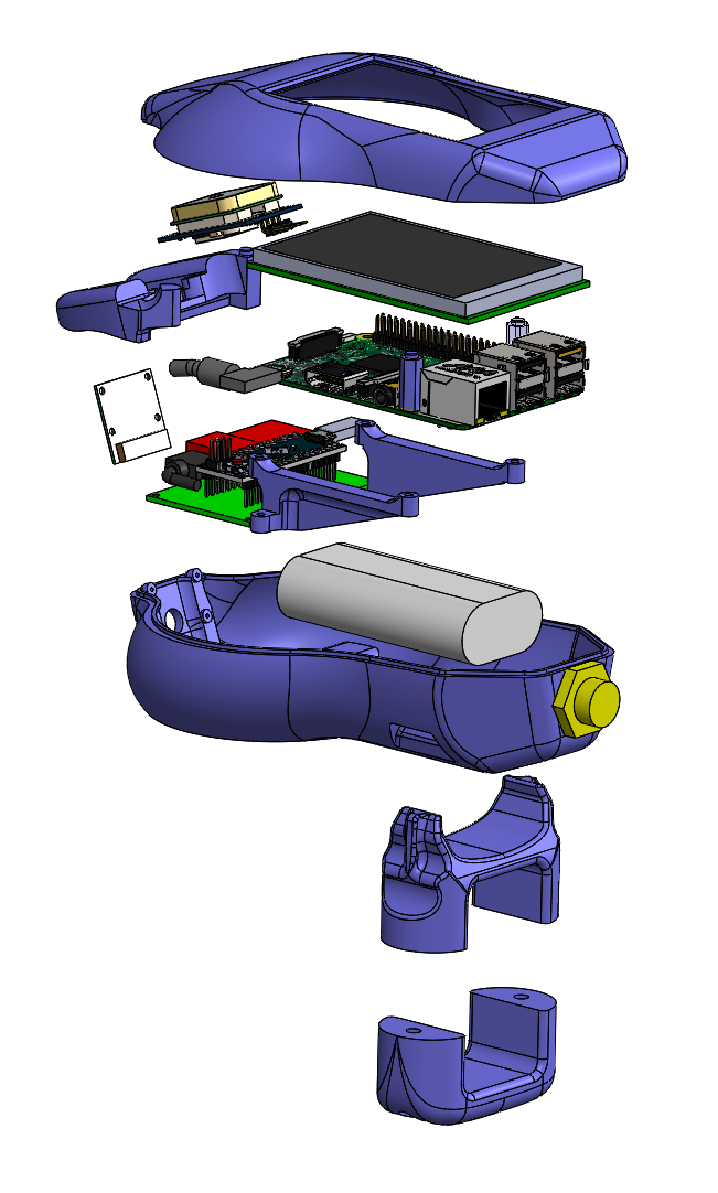 Exploded View.
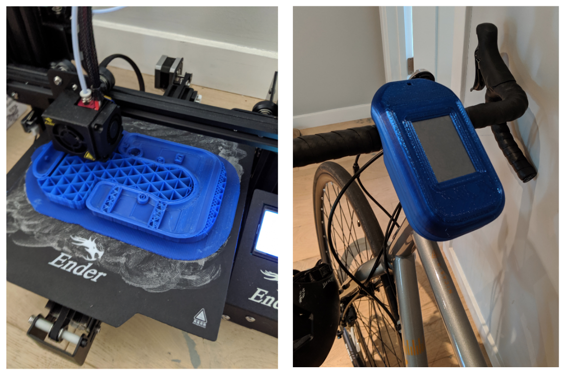
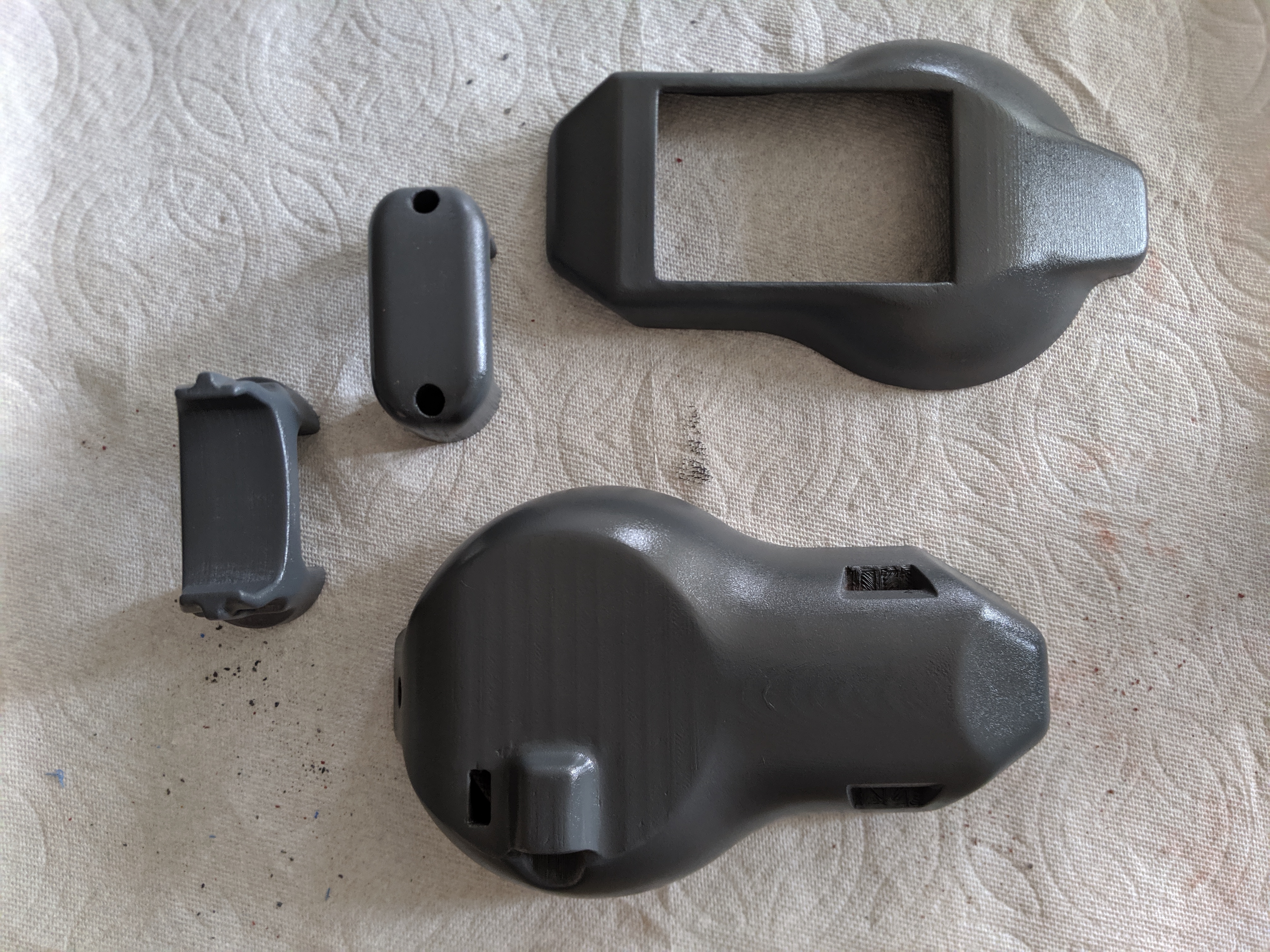
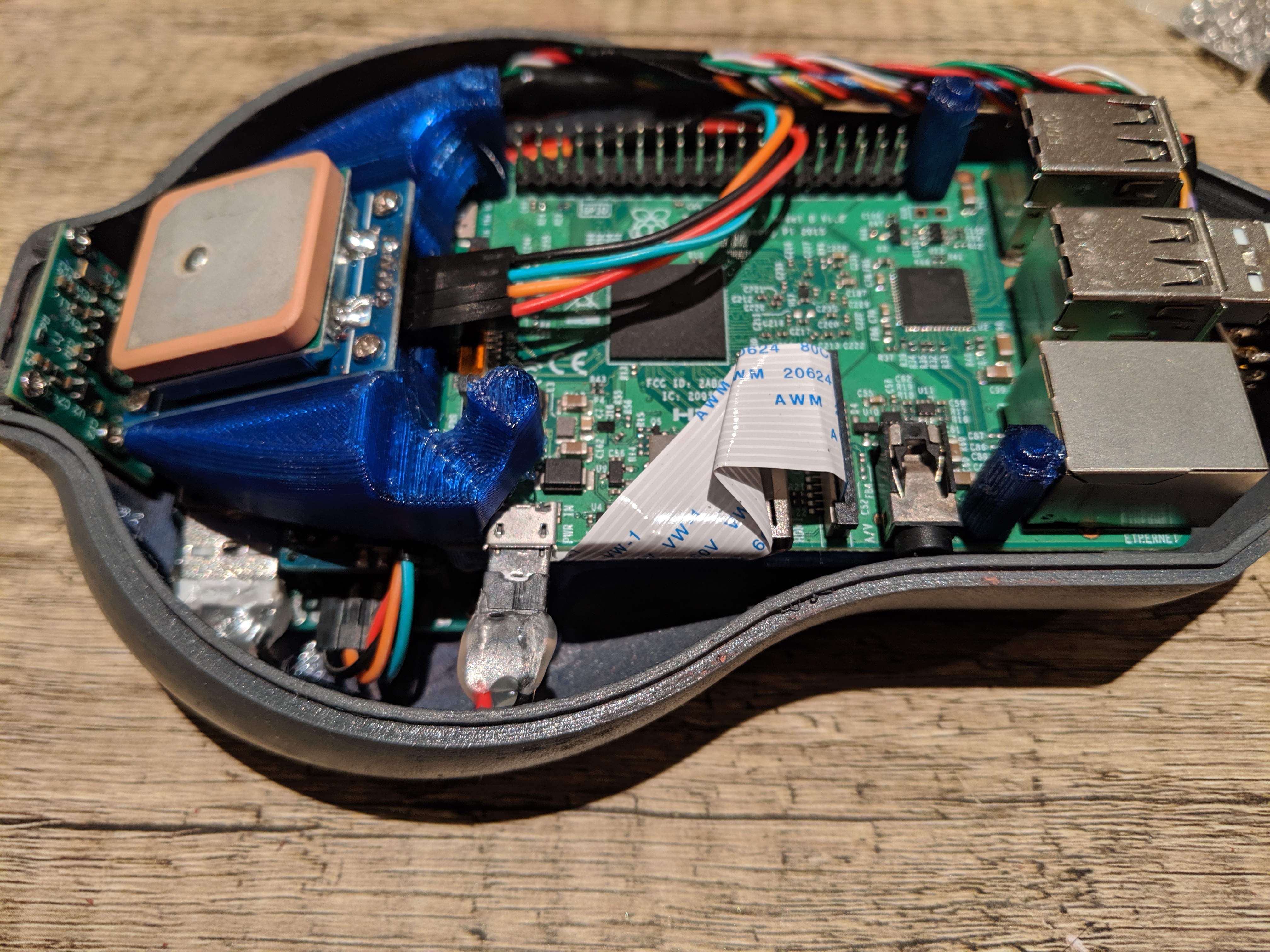
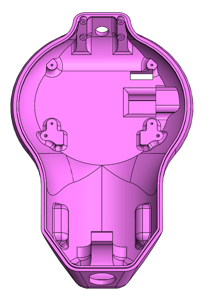 The lower enclosure is the most complex part, having the most interfaces to other components, and requires about 11 hours to print with the settings I’m using.
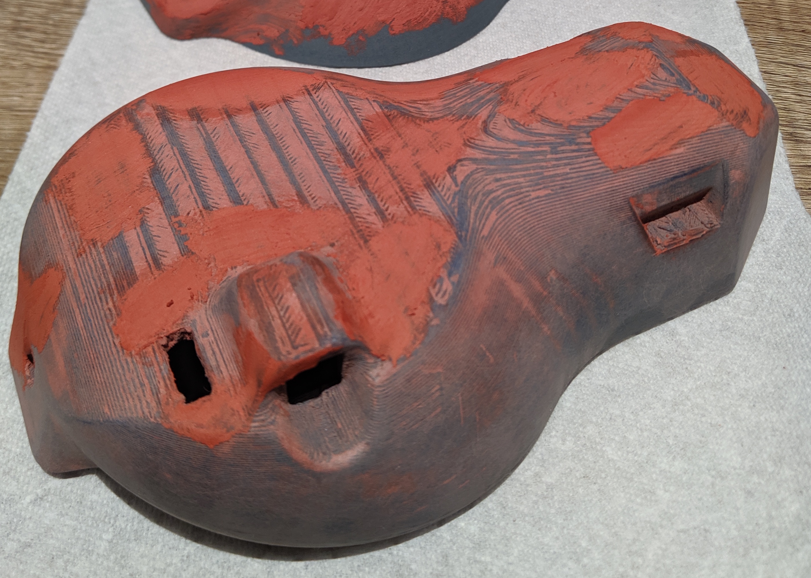
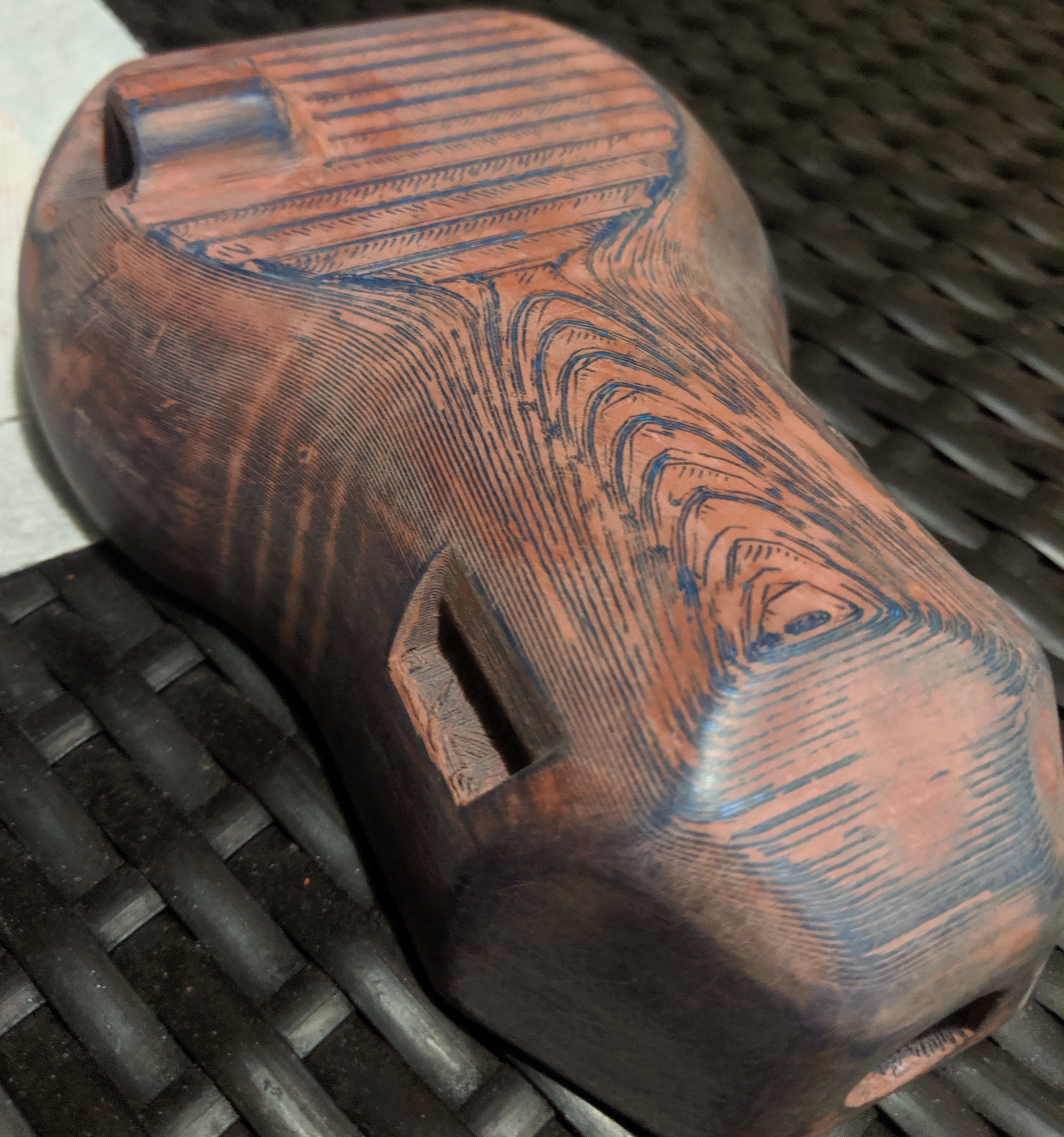
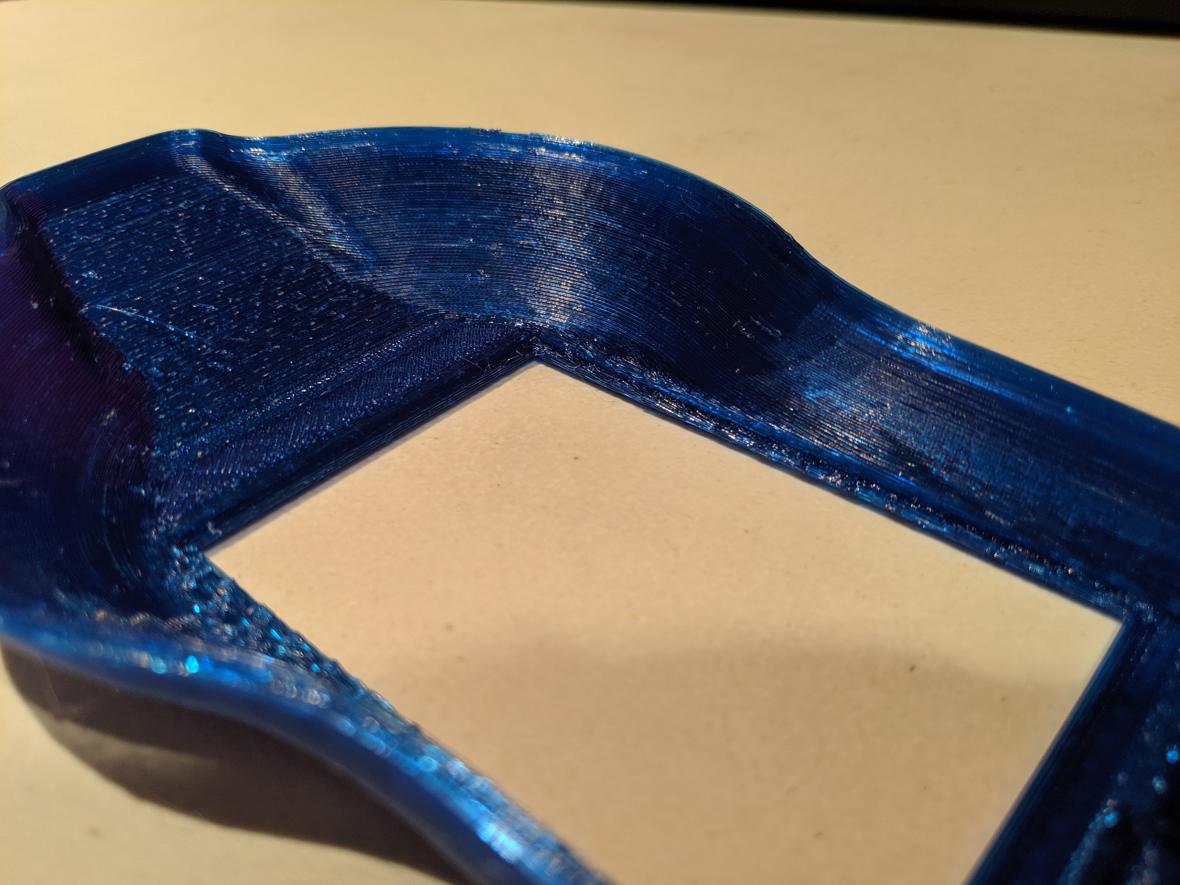 The enclosure sealing surface is at an angle to the screen sealing surface. I prioritize the larger enclosure sealing surface to be flat, which resulted in the other surfaces to come out a bit jagged due to the resolution of the printer. I might try sanding down a bit, otherwise I could just use a gap filling silicone adhesive to seal the uneven surfaces.
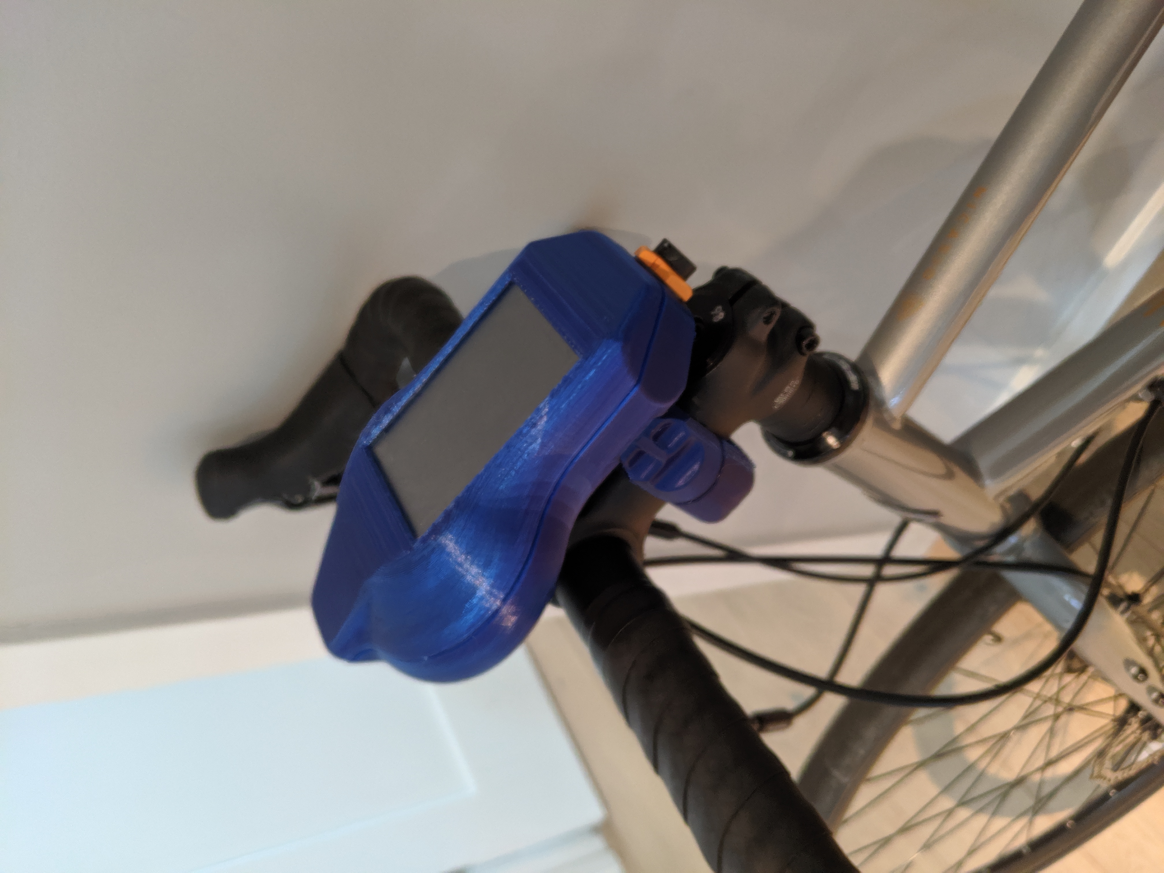
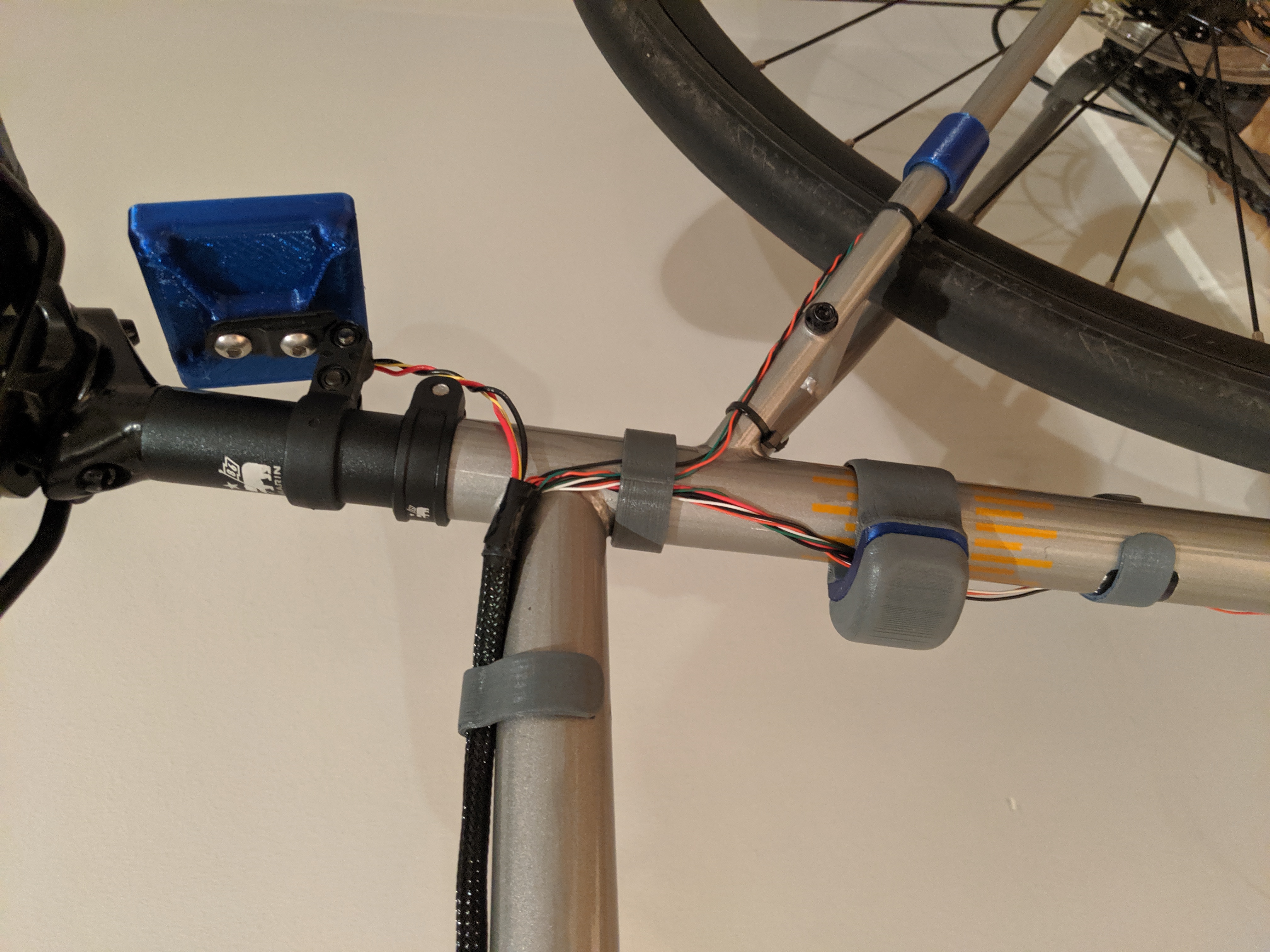
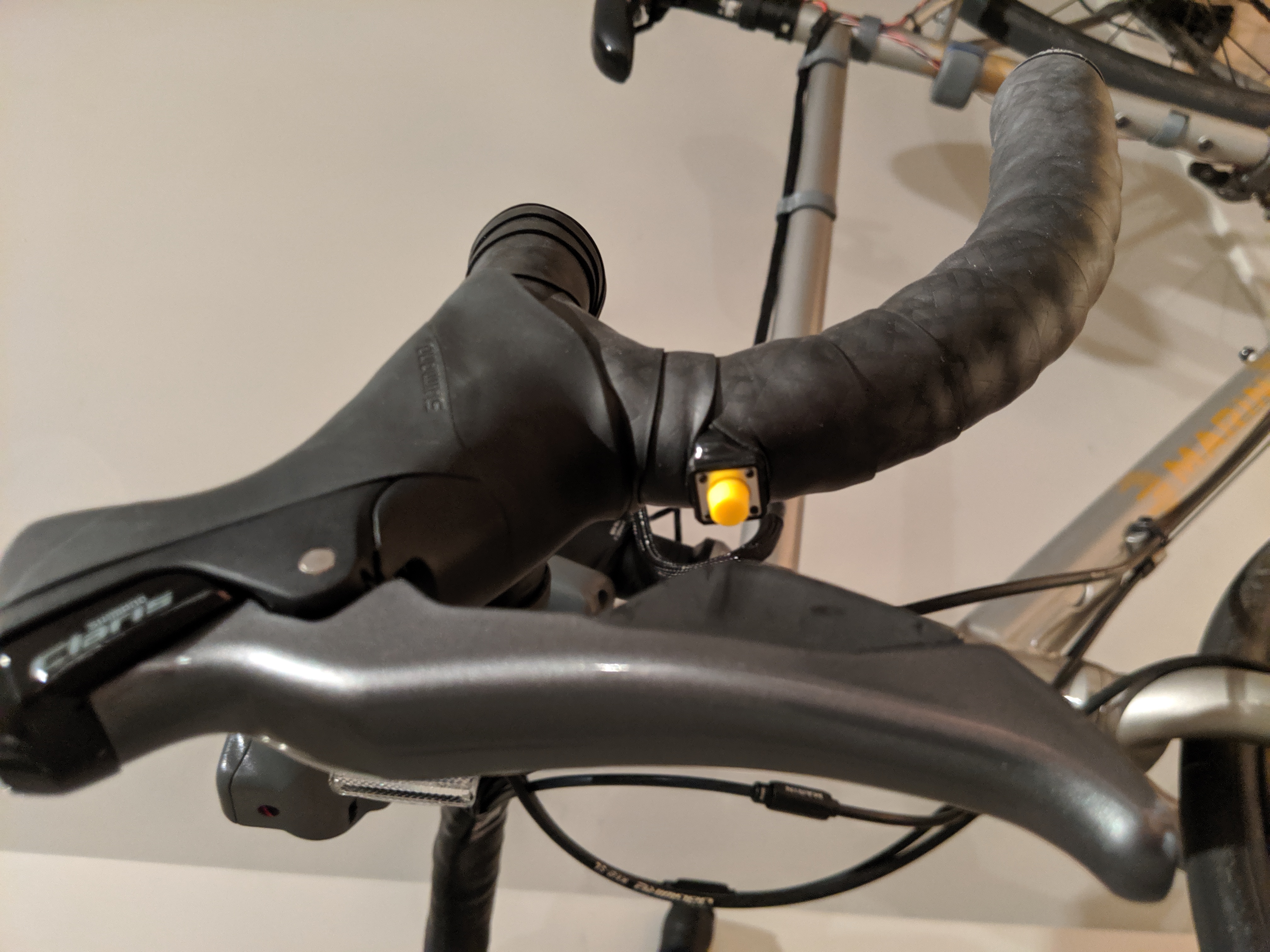
To clamp the computer to the bike, I designed a snap fit pincer type mount that would hook into depressions in the base of the enclosure. This provides a sturdy connection while also being easy to remove the computer from the hold by hand.
 I designed all custom parts in Solidworks, including the enclosures, bike clamps, internal mounting brackets, and the layout of electrical components on the internal PCB. The parts were printed in blue ABS, and were finished later. The electrical components are hand soldered to a through hole breadboard PCB.
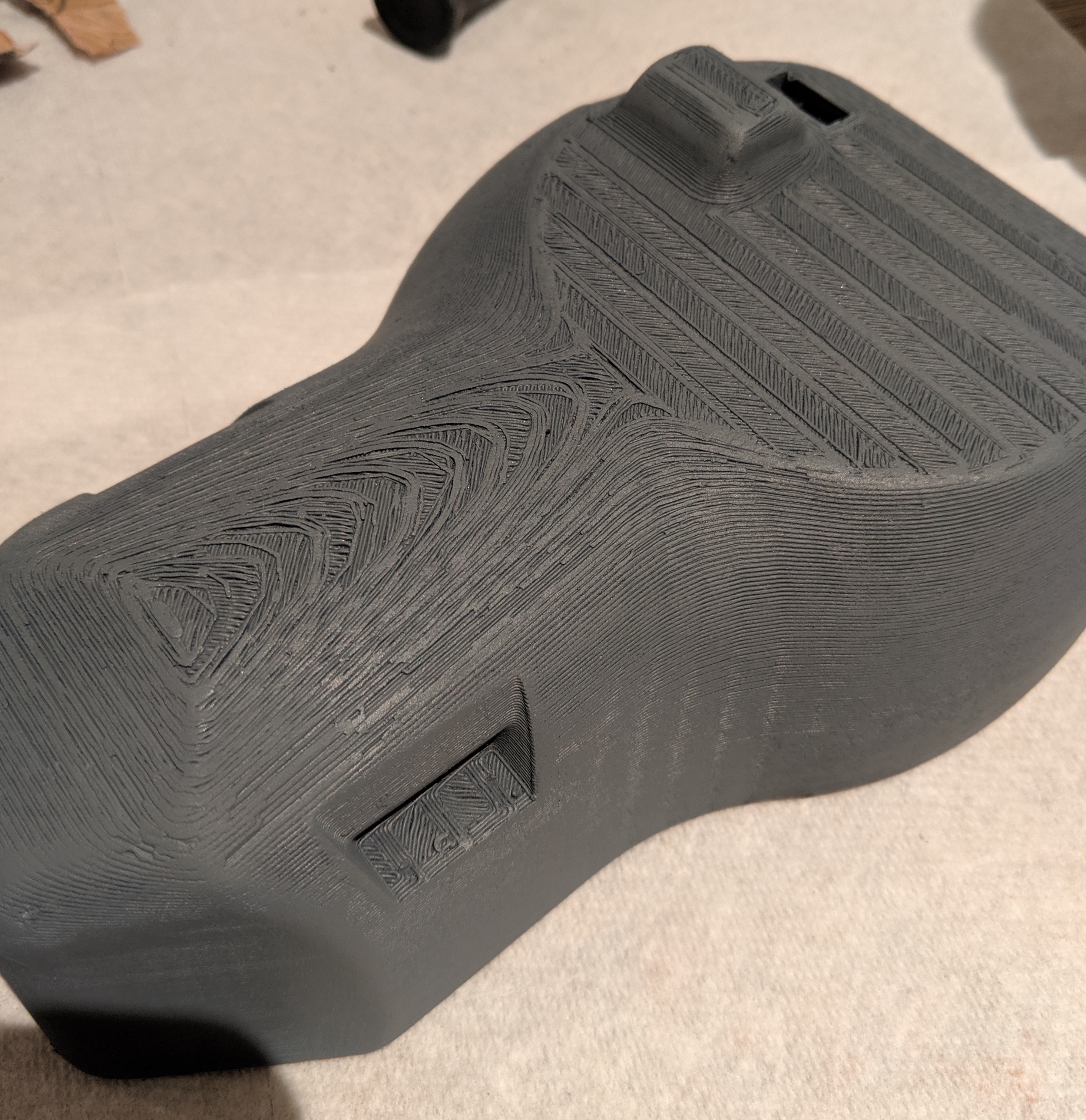
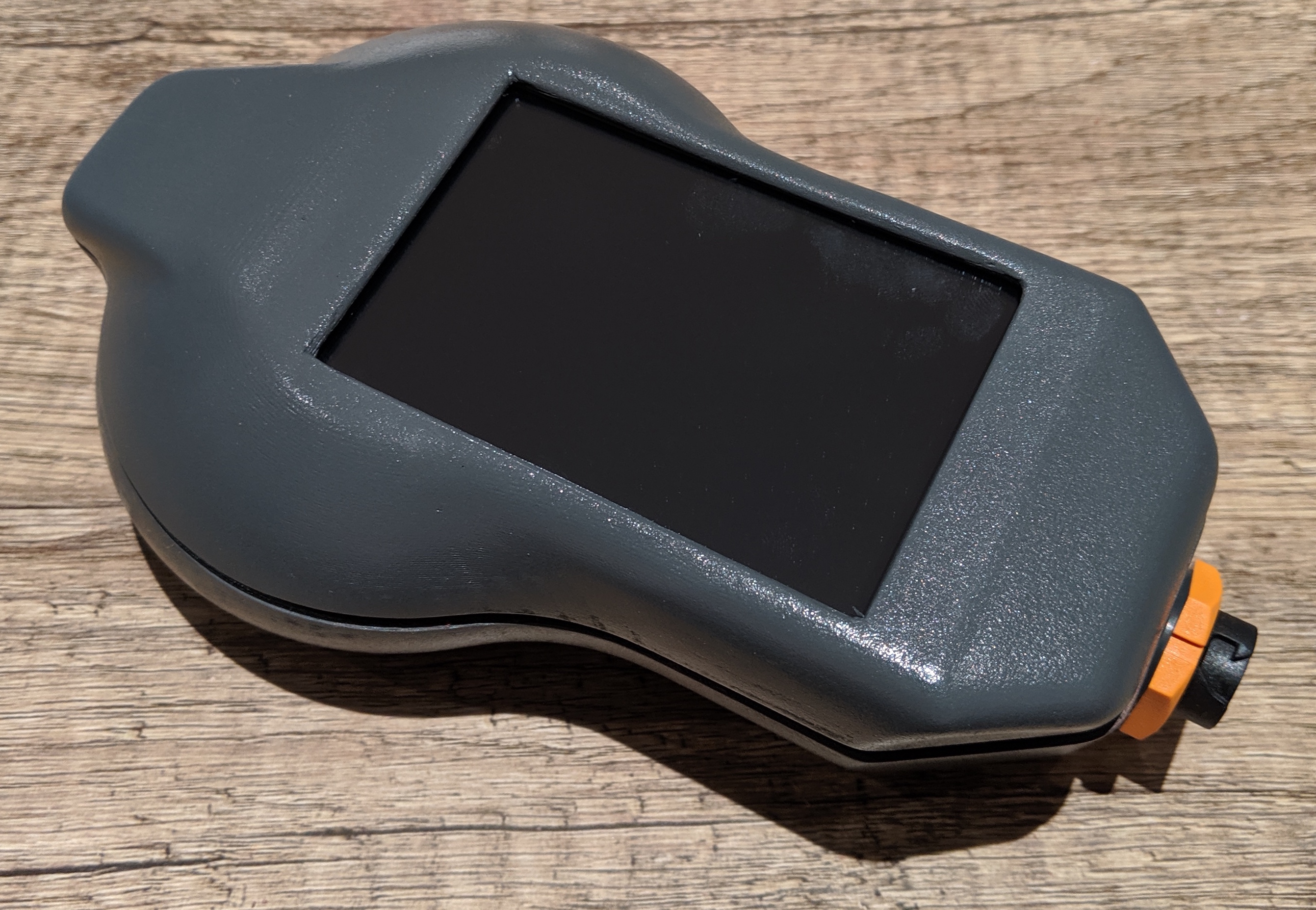
The finishing process for the parts consisted of sanding down the fresh 3D printed surface between 220 and 600 grit, applying primer, repeating the sanding, applying bondo, repeating the sanding, and then doing two coats of the final paint. I used a glossy gray spray paint for the final coat, which I think came out quite nicely, and matches with teh color scheme of my bike.
Electrical Design
A 2200 mAh battery was used for this system. Summing the current consumption of the Pi, Arduino, camera and LCD screen, this gives over 2 hours of continuous use before recharge. With the brake lights on, this could be reduced to 1 hour.
I’m using standard USB connectors to deliver power and send data. I cut open off the shelf USB cables to reduce the packaging size of the protruding connector and get the right cable length for all the intenral connections. The Arduino will send info to the Raspberry Pi via a serial connection.
A few wiring harnesses were made to pass power and signals across different boards and ports. I made sure to add some hot glue at the connector ends to strain relieve the wires from the connectors, and give enough slack for service loops and assembly.
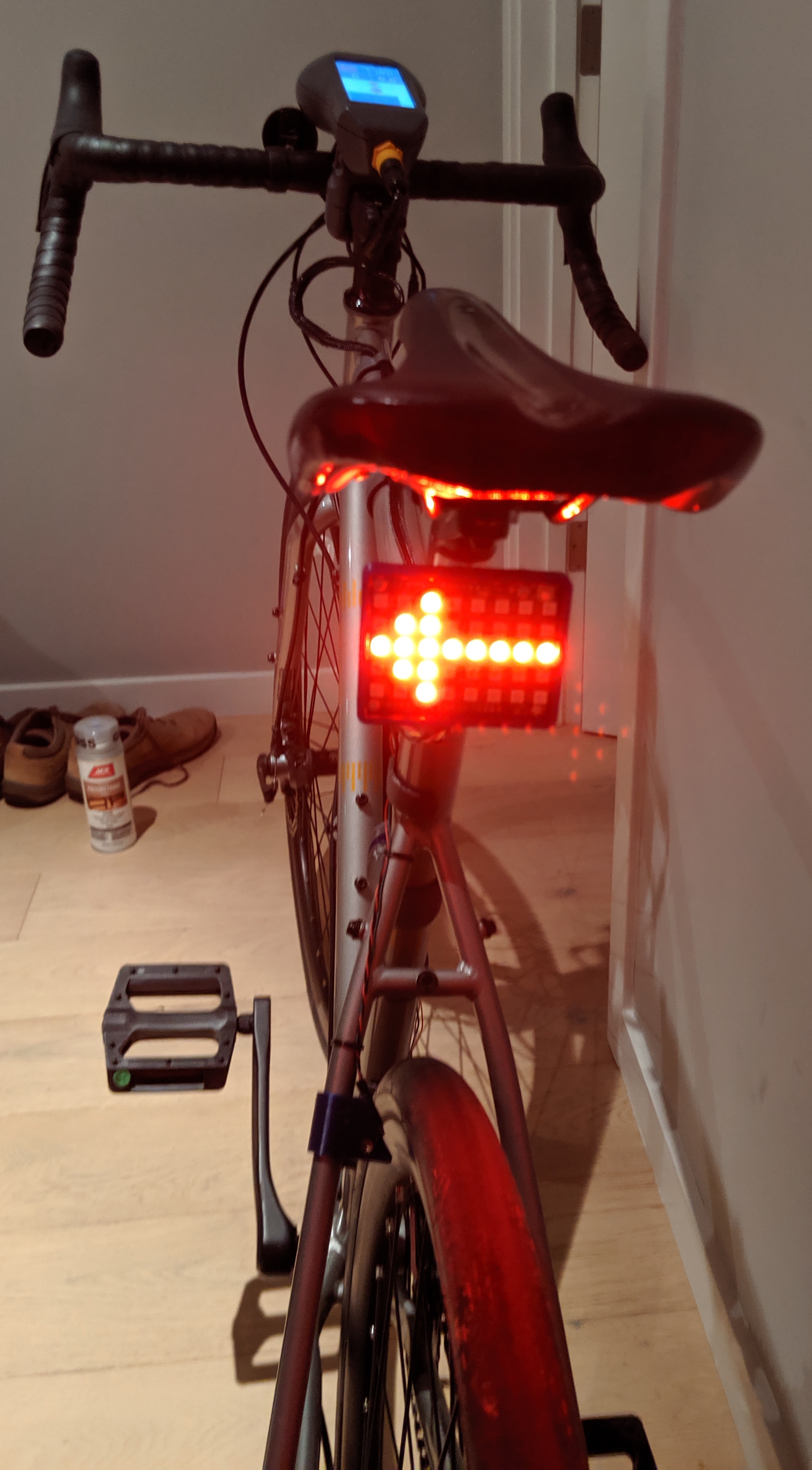
Shown in the right image is the IMU unit on the bottom, the Neo-Pixel light panel on the top, and one of the hall effect sensors on the right.
The camera connects to the raspberry pi via a flat flex cable, which I had to crease a few times to get the correct routing. Its adhered to the unused HDMI port with VHB - we’ll see how this cable holds up over time.
Software Design
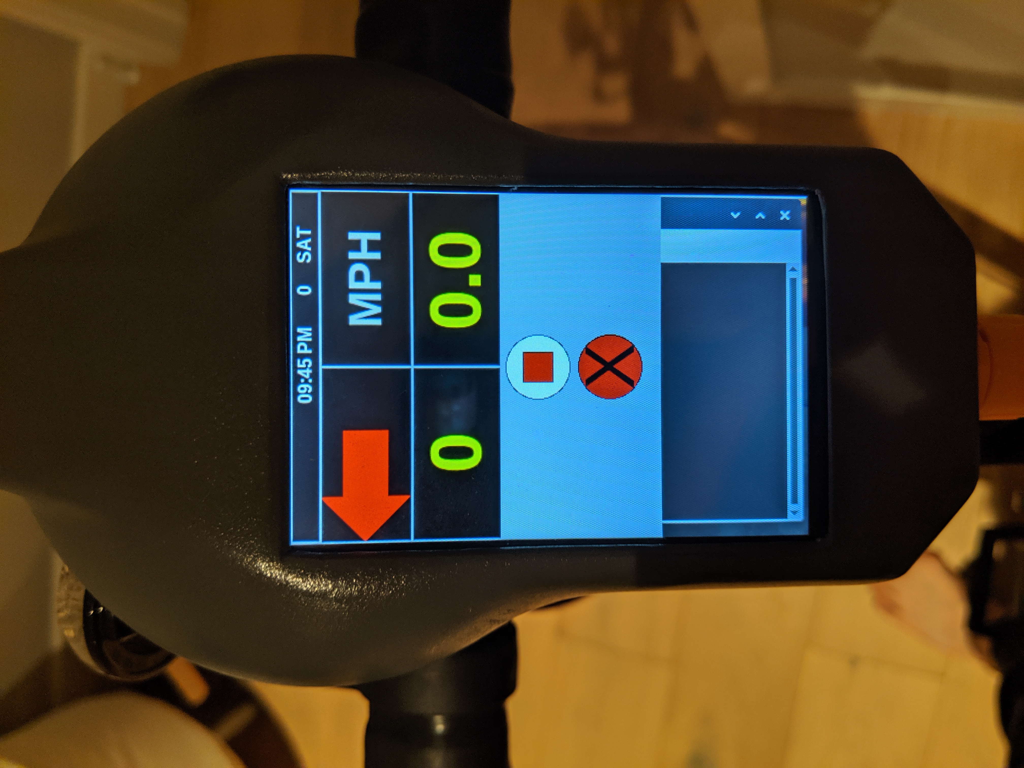
I’ve started on a touchscreen interface for bike info display. It shows speed and pedal cadence based on the hall sensors, as well as indicators on the blinker state, and the current time. I also have buttons to start/stop the logging of all bike data (including GPS and IMU) as well as a program exit button.
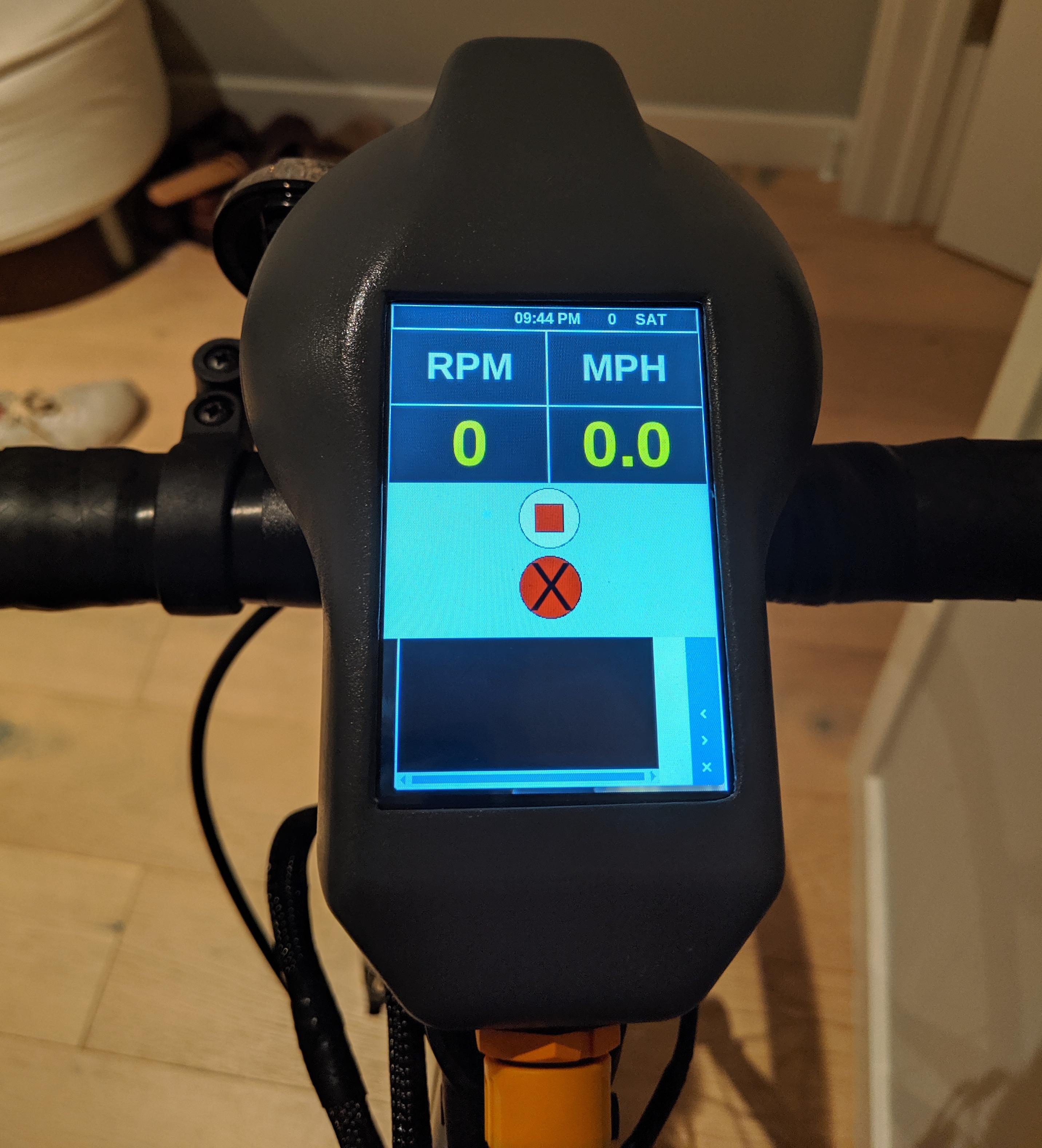
Concurrently, the camera up front records continuous video as the program is running, storing them for viewing later if needed. The next steps are to incorporate the GPS data and road map data to display my location on a pannable map. More to come.